Thursday, September 30, 2010

Bulding An Electric Motor

Thursday September 30, 2010

Today the class had to build an electric motor.

The materials we used were, a power supply, paper clips, an axle, commutator pins, cork, armature wire, nails, thumbtacks, strips made from aluminium cans, and magnets.
The motor itself was made out of a cork tap, and coil wrapped around it.

Wire was filed at the ends and twisted around the cork. The ends were filed down, so the wire would conduct electricity at the part where it was connected to the commutator pins.
The motor was stuck on an axle and supported up by paper clips.
Commutator pins were placed at ends of one of the faces of the cork tap in a way that when the cork span, the two commutator pins touched the aluminium strips (brushes). The purpose of the aluminium and the commutator pins was to pass on a current which made the motor spin.

When we wound the piece of wire around the cork tap we were able to use up most of it, however we had to cut a small portion. If we used more of the wire, the motor would have spun more easily. It is possible that the ends of the wire were not touching the commutator pins, or were not properly sanded down, which caused the current to not complete its circuit.
When we nailed the four inch nails, we left too much space and had to re-hammer them closer together, so the magnets would stick. We did not hammer them down very well, and the construction was unstable.
There was another problem with our motor. The strips of aluminium we cut out were too long and thin. They ended up getting caught in each other on top and not touching the commutator pins properly.
The commutator pins we used were too short. They did not contact the aluminium strips. When they were in the cork far enough to be stable, they did not reach all the way to the aluminium strips. We realized we needed to improve the motor.
Tonight we will work on rewinding the coil, and filing down the wire to make sure that the current is passing through the motor so it can spin. We will also cut out more stable strips of aluminium and longer commutator pins, so that they contact each other.
Also we will add something on the ends of the axle so that the motor does not move up and down the paper clip supports. We want to make sure the motor spins at a stable spot, so that it touches the aluminum strips, every time it makes a turn.
Another change we will make is to make the holes inside the paper clips larger, so that they offer less resistance to the axle of the motor when it spins.

Hopefully by making those changes, our motor will work and everything will be fine with our motor.

One thing that we did nicely was to keep our board clean and organized. The motor was attached on the axle nicely. The paper clip supports were even.
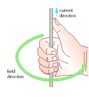
Motor principle refers to the force produced between a magnet and an electromagnet. An important application of this principle is the electric motor. It directs electric force full circle.

These are pictures of our motor in the process.


Sunday October 3, 2010

By Friday, we had completed our motor and tested it in class. We were excited to see if the improvements we worked on would really make our motor work more smoothly and perform better.
When we attached the magnets and power supply we were disappointed because our motor did not spin.
At first we thought the problem was with the strips of the soda can and the coil. We were about to take off the coil and sand the edges better to allow for better conductivity, when Mr. Chung found out that there was something wrong with the wires used to connect our motor to the power source.
We were happy that our hard work payed off.

This is a picture of our completed motor before we tested it. It was spinning very smoothly.

Wednesday, September 22, 2010

Magnetism and Electromagnetism; Right Hand Rules

Oerstead' Principle; the charge moving through a condutor produces a circular magnetic field around the condutor.

RHR1
Grasp the conductor with the thumb of the right hand pointing in the direction of the conventional (positive) current flow. The curved fingers point in the direction of the magnetic field (around the condutor.)

RHR2
Grasp the coiled coductor, with the right hand. The curved fingers should point in the direction of the conventional (positive) current flow. The thumb should point in the direction of the magnetic field within the coil. The thumb also represents the north (N) end of the electromagnet produced by the coil.


Monday, September 20, 2010

Magnetism and Electromagnetism

- A magnetic field is the distribution of magnetic force in the region of a magnet.

- North and South are the two different magnetic characteristics. They are responsible for magnetic force.

- Similar magnetic poles (i.e. north and north, or south and south) repel one another.

- Dissimilar poles (north and south) attract one another with a force at a distance.

- To map a magnetic field we need to use a test compass.

-The Earth acts like a giant magnet, producing its own magnetic field. It is suggested that this magnetic field is produced because of the flow of hot liquid metals inside Earth.

- Magnetic forces act on ferromagnetic objects (certain metals that are not magnets.) Some ferromagnetic metals are iron, nickel, and cobalt. They have atomic structures that make them strongly magnetic.

-Domain Theory:
All large magnets are made up of many smaller, and rotatable magnets, called dipoles, which can interact with other dipoles close by. If the dipoles line up, then a small magnetic domain is produced.


Tuesday, September 14, 2010

Resistance - Ohm's Law


The amount of current that flows through a circuit and the amount of energy transferred to any useful devices is dependant on the potential difference of the power supply and the nature of the pathway through the loads that use the potential energy.

 
The more difficult a path is, the more opposition to the flow there will be. The measure of this opposition is called the electrical resistance.

 
                  Resistance = Voltage / Current     or        R= V / I

 
The measure of resistance of a substance is called the resistivity. It has units called the ohm.

Resistance depends on a conductors' length, cross-sectional area, the material it is made of, and its temperature:

 
  • A larger cross-sectional area of a conductor offers less resistance to the charge flow.(If the cross section is doubled, then the resistance goes to half of its original value.) 
  • A longer conductor has greater resistance than a shorter one. (If length is doubled, then the resistance is also doubled.)
  • Generally an increase of temperature of a conductor, usually contributes to an increase in the resistance but not for all substances.

 
In a series circuit the loads are connected one after the other.

 
In a parallel circuit the loads are connected side by side.

 
In any circuit, there is not net gain or net loss of energy.

 
Resources:

 
Ohm's Law and Resistor Circuits
Ohm's Law
More on Ohm's Law

Saturday, September 11, 2010

In Class Challenge 10/9/2010 and Parallel vs Series Circuit


The major difference between a parallel and a series circuit is in the way that the loads are connected. In a parallel circuit the loads are placed side by side.


In a series circuit however, the loads are connected one after the other in one path.

Each arrangement has an effect on the way in which potential difference and current act in the various parts of the circuit.

Kirchhoff's Current Law
The total of the current that flows into a junction point of a circuit is equal to the total amount of current that flows out of that same junction.

Kirchhoff's Voltage Law
The electric potential difference (voltage) of the battery (energy source) is equal to the total of the electric potential differences of the loads combined.


Kirchhoff's laws help us determine that in any circuit there is no net gain of electric charge or any net loss of energy.

In Class Challenge

Our class was split into groups of four and given an energy ball each.
My group could make the energy ball work by placing our finger over the hole that separated the two pieces of metal. The ball began to flash and hum because that way the circuit was completed.
A finger is a conductor. A metal is a conductor. By connecting the two pieces of metal with our fingers, we let the electrons flow and finish the circuit. We had to touch both metal ends, because by only touching one, the circuit does not complete.
The ball will not work if you connect the contacts with any material. For example, it will not work with glass, plastic, rubber, air, or wood. The material used has got to be a conductor of electricity.


The energy ball works with anything that allows electricity to pass through. The material has to be a good conductor, for example, silver, gold, copper, aluminium or any other metal. According to the results of the activity, human skin completes the circuit and allows electricity to pass and is therefore a good conductor.
The ball does not work on individuals who try to close the circuit with their hair or clothes. That is because water is lacking. Water acts as a conductor only when metallic solids are present in the water (so that the water is charged and the particles are free to move.) The ball might not work on individuals with a certain condition or disease or dehydration.
For more information see: Is water a conductor of electricity?

The ball lights up with all four individuals in my group if we connect the circuit properly (complete the circuit.)
With one energy ball we can create a simple circuit. All the parts are simply connected.
Given two balls we can create a circuit where both balls light up. We can form a series circuit.
if one person lets go of the other person's hand (while they are acting as a part of the circuit) they will act as a switch and make the ball go off.
It does not make a difference of who lets go of the other person's hand. Circuit is broken nevertheless, if it is a series circuit. In a parallel circuit it is possible to have one energy ball on and the other off.
It is possible to create a circuit where only one ball lights up. This can be achieved by making a parallel circuit.
The minimum number of people needed for this circuit is four.

Resources:

Source 1 for Pictures

Thursday, September 9, 2010

9/8/2010 In Class Challenge


In this challenge the class was split up into groups of three people and had to build the tallest structure, using a piece of tape and five pieces of newspaper. The rules were that the structure had to stand up by itself and be portable. The tallest structure built was around 160 cm.
My group first tried to make a structure out of rolling the pieces of newspaper into equal cylinders and stacking them on top of each other. That did not work however, because firstly, the pieces were very not stable, and the structure was too heavy at the top for the base to support it. We rolled the paper at the top, adding unnecessary weight. In addition we did not use the tape very reasonably, because in the end we were left with parts of the structure's top that were not stuck together properly and kept breaking. We set two pieces of newspaper aside for the base which we rolled into a ball and stuck the tower of our structure in. Because we could not stick the base to the ground our structure ended up falling.
I noticed that most of the successful structures in the class (i.e. the tall and stable ones) had a tripod base.

If I had to redo the challenge i would put less weight on top of the structure (by rolling half a piece of paper instead of a full one), and make the base wider.

Physics of a Tall Structure
- wide base
- use of triangles
- heavy base
- adding more support points
- taper the structure by making the top less heavy and skinnier
- a lower center of gravity makes it easier for the building to balance

The center of gravity(often called the center of mass) is the mean location of the mass in a structure. In order to stabilize a structure, engineers need to locate the center of gravity of a structure, and also distribute the mass of the structure evenly around it. The force of gravity acts on everything (i.e. all parts of the structure) so if the weight of the structure is distributed around it evenly, the structure will be stable.

For structures built outside the foundation on which they are built must be stable. The foundation must not be very moist. Also if the type of foundation is not taken into account, the structures may get cracks in their walls and the foundation.

Resources:
http://www.edquest.ca/component/content/article/156
http://www.grc.nasa.gov/WWW/K-12/airplane/cg.html
http://wiki.answers.com/Q/What_makes_a_structure_stable
http://wiki.answers.com/Q/What_are_some_ways_you_can_make_a_structure_more_stable
http://www.allenandunwin.com/_uploads/BookPdf/TeachersReview/9780713676884.pdf

Wednesday, September 8, 2010

Current Electricity and Electric Circuits

Physical Quantities and Measurements:


          Charge (Q) measured in coulombs (C)


          Current (I) measured in amperes (A)


          Time (t) measured in seconds


          Electrical Potential Difference (Voltage) measured in volts (V)


          Energy (E) measured in joule (J)


Facts Learned:

•  Current is the total amount of charge in Coulombs that goes through a point in a conductor, divided by the time it takes. Current is symbolized by I. The formula is:
 I (Current in Amperes) = Q (charge in Coulombs) divided by t (time in seconds) or I = Q / t

• The base unit for current is C/s which is named Ampere. It is represented by (A). One ampere = one Coulomb of charge moving through a point in the conductor / second.

• Conventional current flow vs. electron flow:
              - Conventional current flow is from positive to negative.
              - Electrons are negative and flow from negative to positive.

• Voltage vs. Current

              - Voltage is the electrical potential difference between two points.
              - Voltage would move from a point of higher potential to a point of lower if given the chance (until the levels equalize).
              - Current is the rate of flow of charge.

• In coloured writing convention used to keep track of electron current flow, black represents the negative terminal and red represents the positive terminal.

• In a direct current, the current flows in one direction. It flows from the power supply, through the conductor, to a load, and back to the power supply.

• In an alternating current the electrons reverse the direction of their flow periodically, with the help of electric and magnetic forces.

• Work is done by the power supply to increase the electrical potential energy of each coulomb of charge from a low to a high value. As the charge flows through a load, its energy decreases.
The electric potential energy (voltage) for each Coulomb of charge in a circuit is called the electric potential difference.

• The energy (needed to do work) = electric potential difference * charge or E = Q* V

• 1 Volt is  the electric potential difference between two points (if 1 joule of work is required to move 1 coulomb of charge between 2 points.


Resources:

     http://www.differencebetween.net/technology/difference-between-current-and-voltage/

     http://www.wordiq.com/definition/Potential_difference       
     http://www.educationalelectronicsusa.com/p/current_electricity-I.htm


Video:
You can aslo check the Video on Electric Circuits